Required Vocabulary:AC: Articulating Current
AC ESS: Essential AC Bus
APU: Auxiliary Power Unit
BTB: Bis Tie Breaker
CSD: Constant-Speed Drive
DC: Direct Current
DC ESS: Essential DC Power
Gen: Generator
SSB: Split-System Breaker
TR: Transformer-Rectifier
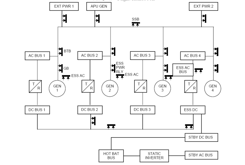
Schematic Diagram
(This schematic is from a Boeing 747. If you are dealing with a two-engine aircraft, it is more or less the same, minus two of the generators.)
IntroductionSomething familiar to you all in a plane is the need for electrical power, however, for a GA plane, this process is as simple as flipping the batteries on, switching on the Avionics Master, and that's it. In a jet, the electrical system is a LOT more complex. Today, you will learn about the Generators, the CSD, the difference between AC and DC power, the APU, and so much more...
Ground PowerThe process is simple enough, there are receptacles for a Ground Power truck in select areas of the fuselage, and they simply plug themselves into the plane to power you. the process of actually providing power is a lot more complicated, though.
APUThe APU is a backup power supply for the aircraft that is used when the engines are offline and when External Power carts are not available. It works just like the ground power carts, except you only have one APU. By the way, the APU is considered by me an engine, as it operates almost the same way and consumes fuel.
CSDThis is the first step of providing power through the engines. This is needed because the generators can only generate enough power to power the aircraft if the engine drives are turning at a specific rate. The CSD is specifically designed to do that. It rotates at the exact speed required to provide optimum power to the plane.
Why does the APU not have a CSD? Because it only has two speeds, none, and full. (The APU is its own CSD)
Field RelayThese use a specific logic to determine the current output for a specific generator. This is read by the Engineer in Volts and Amps
GeneratorsEach individual engine has its own generator, driven by the CSD and monitered through the Field Relays. Electric currents entering the generator are measured in KWs or KVARs.
Schematic Explanation(All the bolded black lines with the arrows pointed to them are the circuits that modulate when opened or closed.)
Let's follow the yel...black...pixelated.... road.

So, you connect the Ground Power to the plane, and close the circuits to link the Ground Power with the plane. The SSB MUST remain closed at this time (Only if you are operating with two power carts, if one, close it), as you cannot link two Ground Power cart circuits together. Next, you want to close the BTBs to link the current with the the main AC buses. What does this do? A lot.
Look back to the schematic, and you will see that the AC buses are linked to the TRs. These operate to transform an AC current into a DC current, and each TR is linked to a DC bus (1, 2, 3, and ESS). Although you cannot see it on the schematic, these DC buses have a direct link to the Batteries, and are now charging them. See, the batteries themselves are only capable of supplying a DC current, and not for very long. It is highly important you hook up the External power or the APU before you run out of juice.
The ESS DC Bus is linked to the STBY DC bus, which will take over for the ESS DC Bus in case of failure, The Hot Bat bus, which supplies emergency power to the plane in the case of a full electrical failure, the Static Inverter, and the STBY AC Bus. These are your fail-safes for a full electrical failure on the plane, where the Hot Battery bus supplies DC power for only essential instruments, and the Static inverter converts the DC Current to AC to supply essential AC power.
Now, the Generators operate differently from the External Power plugs and the APU. After turning on the CSDs and Field relays, the Generators start generating power. Afterward, you close the Gen Buses, linking the Generators to the previously explained electrical system, and finally, you close the Bis Tie Breakers to have the generators share the job of powering the plane. (SSB can be closed, the currents can be linked.)
That is a detailed explanation of how the electrical system on a jet works.


