Ripping Into An AxisPad FX GamepadI am continuing working on using the Axispad FX gamepad as the basis for a USB "interface card" to utilize the multiple buttons and the double joysticks it contains for mapping to other functions.
(See earlier posts in this thread.)I now have all the wiring connections soldered in place on the gamepad circuitboard itself. The next step is to mount the Axispad circuit board onto another piece of perf board for stability, and then to hook the various wires onto connectors that will serve to easily hook up the controls that will be located in the simulated cockpit.
Mechanically these "surface solder connections" are NOT the best and most stable way to connect things. But this circuit board is double sided ...so drilling a little hole at each solder location is not possible. So getting the whole thing as rigid as possible as soon as possible is a good idea.
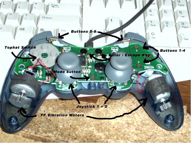
Here in photo #1 is the Axispad FX with the top cover removed before I have done too much to it. On the right side, the rubberized plastic button covers have been removed showing the copper trace contacts that the conductive material that is on the back side of the rubberized button sheet makes contact with. It is onto these traces that you need to solder new wires to remote the closure connection out to other buttons located on your panels.
I am not sure what I will be doing with the outputs for the two force feedback vibration motors. Their use intrigues me.... and I may see what can be done with them. I have to figure out what command in the sim would cause them to activate. I expect it will be in the aircraft.cfg file under the force feedback section...... but I don't know anything about that yet. Any thoughts anyone ???. More on that research MUCH later.
Photo #1

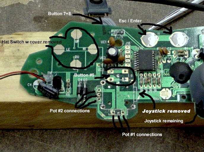
Here below in photo #2 is more of a close-up of the circuit board before I have added new wiring. The left joystick is already removed. You can see that some of the switch traces have contacts that are pretty simple to solder onto..... big flat planes of polished copper. Some however... like buttons 1-4 in the upper right and also the "mode button" in the center bottom...... have little tiny "fingers" of copper traces that intermesh. These take some really careful work. On some of them I used an exacto knife and cut some of the "fingers" to make the soldering easier to do.
Some of the buttons activate by bringing the hot side to "ground". So for these buttons you only need one lead.... and use a common "ground" connection for the other lead. So that is why you don't see "pairs" of leads coming off each button point on the circuit board. Some buttons do NOT work this way so they have two leads. The top hat buttons are like this.... and each "pair" of buttons has a separate second lead. So if you look close at the last picture, you'll see four red wires on the tophat button section....and only two black wires.
Buttons number 9 and 10 (not seen) seem to have four contact points on the pc board...... but in reality only two of them for each switch are actually connected to anything if you study the traces. If you look at the last picture... you can clearly see the two wires connected at the diagonal corners of button number 9's position.
On the pot connections where the joysticks used to be, the two end holes on the pc board of each set of three holes see the full 10K ohm constant resistance of the potentiometer. The center hole is where the variable resistance is "read". The color coding on the pots is red, black, green wires.....with the black being the center variable connection.
Photo #2

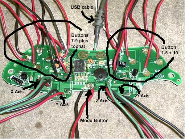
In this last shot all of the added wiring in now soldered into place. The wires are sort of now grouped into four "sections". The top left and right are bundles of what will be various control buttons. The lower left is the two axis connections for one joystick ....which are now really just "analog inputs" onto which I can now attach 10 K potentiometers. The lower right side is the two axis connections for the other joystick.
In the center bottom is the switch connection for the "mode" button. The Axispad needs to be set to the analog mode to activate the joysticks. Haven't figured out how to "bypass" this needed keypress. So that button will have to be on the "checklist"

. At the top are two buttons for "Escape" and "Enter". At the moment I don't plan to use them so no wires are soldered onto them. The USB connector that already came on the gamepad is located in the center top.
You'll also notice that the contact covers on the "enter" and "escape" buttons have been removed in the last picture. So now they are not really push button switches anymore. Now they are just little "bullseye" circuit board traces.
Photo #3

So canibalizing one Axispad FX gamepad gets you 14 buttons and four joystick 10K analog inputs to locate onto a simulated cockpit.
So there you have an update on my work on this conversion so far. Hopefully these pictures will be useful if you are planning on trying this modification too....or even one sort of like it.
I'll keep this info coming as it develops. I'm having fun so far

.
best,
.................john

