Simviation Forum
/yabb
Computer Hardware & Software Forum >> HomeBuild Cockpits >> Cockpit Construction (Part 27)
/yabb?num=1147745403

Message started by JBaymore on May 15th, 2006 at 10:10pm

Title: Cockpit Construction (Part 27)
Post by JBaymore on May 15th, 2006 at 10:10pm
Fuel Management Overhead Panel

Tonight I got to working on another one of the overhead panels.  The basic functions of the panel are modeled after the fuel system on the BAe 146-200........ loosely.

This panel is one of the more complex of the bunch I've done so far.  The LED indicators will be powered via local 12 VDC from the simpit main avionics buss.  It will have some in-sim functions that are controlled via the main flight sim computer with the Hagstrom KE-72 connected to that machine.   Other switch functions in the sim will hook to the Phidgets 8/8/8 interface that is bundled with the TextLCD unit which is on machine #2 on the network.  And the Annunciator lights (not done yet) will be lit by a Phidgets LED64 card also on machine #2.  


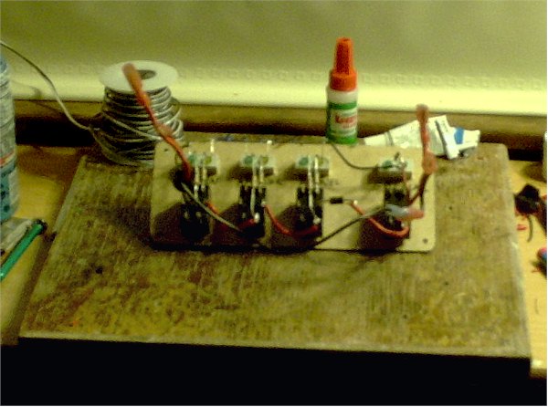
Below is the rear of the panel as I get started routing and soldering the wires onto the switches and indicator LEDs.


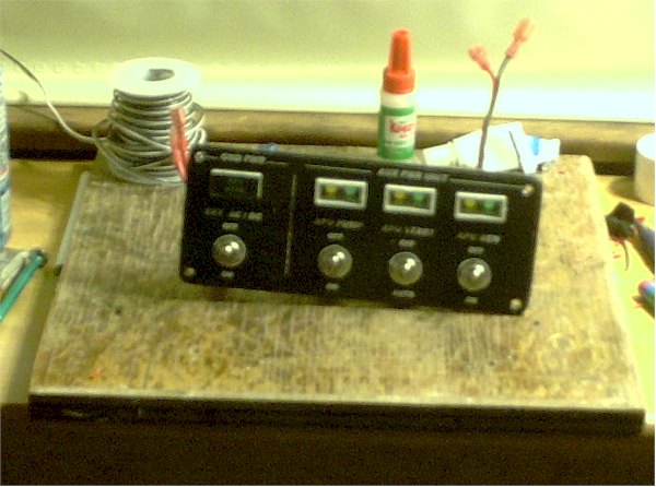
In this shot below you can see the light housings that I have constructed for the "steam gauges" that are at the top of the panel.  These round gauges are really "eye candy" since they do not actually move.  But they are set up as indicators of active fuel pumps on each engine....... when the pumps are on, the backlighting will come on.  In another location on the overhead I have a digital readout of the levels in the tanks on the Phidgets TextLCD display.

The backings for the gauges here are PVC pipe caps, drilled to hold a 1100 mfd white LED in the center.  The LED has had the tip end filed flat and then the whole thing "frosted" with 220 grit silicon carbide paper to give a more even light dispersion in the space.  The LED's have a 1K Ohm resistor soldered in the circuit to control the current.


Below you can see one of the "lights" powered up to test the function.  It gives a nice even light with the "frosted" LED inside the white pipe cap.


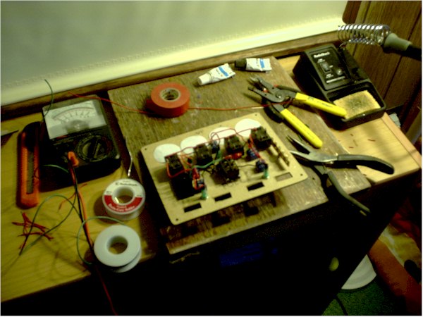
Here is the back of the panel almost completed.  Looks like a plate of spaggetti, doesn't it?   ;)  The blue Cat 5 cable connects to the Hagstrom KE-72.  The straight wires heading to the top of the image will connect to the Phidgets 8/8/8 which is located directly above this panel on the overhead.  The screw connector on the left is the main 12 VDC connection from the avionics buss.


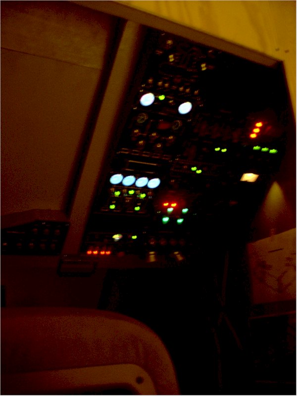
And below is the panel with power applied to test the connections.  Looks good.  Engine pump #3 is not switched on so you can see the difference between the lit steam gauges and the unlit ones.


So......... next is to re-mount it onto the overhead and then start programming the functions.  Then once the Annunciators arrive....... mount and wire them.

More as it happens.

best,

.......................john

PS:  Still having problems with my digital camera in close pictures... sorry.

Title: Re: Cockpit Construction (Part 27)
Post by SilverFox441 on May 16th, 2006 at 2:14am
Very sweet John!

Any plans to make the steam guages work in a later mod?

Title: Re: Cockpit Construction (Part 27)
Post by JBaymore on May 21st, 2006 at 8:06pm
Steve,

No plans to make them active at the moment...... but you never know  ;).


best,

...................john

Title: Re: Cockpit Construction (Part 27)
Post by JBaymore on May 21st, 2006 at 8:31pm
APU Panel Wired

Since the very generous Martyn Becker and I have been playing around with how to be getting an APU relatively functional on a four engine jet modeled in a simpit...... I decided to do the physical wiring on the panel to get ready for when the "in-sim" coding is a reality.

The section to the left of the panel (facing from the front) is the Ground Power section.  The right side is the APU section.

The APU section will require that the APU Fuel Pump is active before it will start.  When battery power is "on" the APU Pump annunciator will light up amber.  When the pump is running it goes to green, and the APU Run annunciator goes to amber.  When the APU is then started, the "run" annunciator goes to green, and the APU Generator annunciator goes to amber.  When the APU Gen is switched "on", the Gen annunciator goes to green........ and on the electrical panel elsewhere the "running on APU power" indicator lights up.


All this will be tied into the sim via the primary Hagstrom keyboard encoder so that aircraft electrical changes happen and a visual and auditory simulation starts up and/ shuts down (mainly thanks to Martyn and with some additional consultation with Pete Dowson).

There are a bunch of resistors soldered on to the various switches to limit the current for the annunciator LEDs as well as some hefty diodes to act as "one way valves" for the current flow to the physical avionics buss in the simpit.  

This panel is one of the four main sources for electrical power for the sim......... battery, ground power, and engine #2 and #3 generators.

The red and black wires projecting at the left side of the back of the panel below come from the parking brake secondary set of contacts...... and emulate "Ground Power".  Ground Power is available only whern the parking brakes are set.

The red and black wires at the right side of the rear of the panel are the main APU electrical "buss" .... that feeds 12 VDC to the rest of the simpit avionics systems.  A similar buss comes from the battery....and from the engine generators.


Here's the front of the panel and you can see the two different color LEDs in each annunciator.


Overhead Lit Up A Bit

Here is a (blurry) shot of the overhead starting to get pretty "lit up" as more and more active panels are added.


So........ that about fills this thread up.  On to the next part soon.


best,

.....................john

Title: Re: Cockpit Construction (Part 27)
Post by flyboy 28 on May 21st, 2006 at 10:10pm
So when do you sell this to BAe, John? :)

Title: Re: Cockpit Construction (Part 27)
Post by Jakemaster on May 24th, 2006 at 2:17pm
So john, Ive been wondering, what do you do to make all the money to build this thing?  I hope it involves electronics, as you seem to be very good at it ;D

Title: Re: Cockpit Construction (Part 27)
Post by JBaymore on May 24th, 2006 at 8:43pm

wrote on May 24th, 2006 at 2:17pm:
So john, Ive been wondering, what do you do to make all the money to build this thing?  I hope it involves electronics, as you seem to be very good at it ;D


Jake,

Rob banks.   ;D  No....seriously.........

I am a professional ceramic artist and adjunct professor of ceramics.  I am a rather late career artist at this point (read that as old).... and through years and years of persistence and determination have finally reached a point of some measure of "success".  

My clay work is in collections public and private, is in art museums in Japan, and published in a number of books and magazines.  In the ceramic art world, my name is known pretty well.  You can go here to see a bit of my work:

http://www.ceramicstoday.com/potw/John_Baymore.htm

In fact, I recently got mentioned (unknown to me beforehand) in a HISTORY book done by Yale University Press called "A Dictionary of New England".  So I guess I am now officially "history".  Now I really feel old!   8)

I am by NO means affluent.....few living artists are.  And the cockpit, ........ while certainly better called a "money pit"....... has not cost me all that much.  

I am a good scrounger.  All of the computers except the main FS machine are freebies.  ALLof the wood, screws, and glue for the whole frame and panels and such cost no more than $300.  Most of the switches are from a local surplus electronics place at no more than $1 each.  Most of the wire is surplus stuff too.  And so on.  It is amazing what some craftsmanship and a coat of the right paint can do  ;).  

The most expensive single component is the Goflight MCP.  

I look at people who buy payware afer payware after payware plane and scenery.  That adds up fast too.  I don't do that.  My "payware" is a single physical plane.....my pit.   This also is my main and only real "hobby".  So I am not spending disposable income on a lot of other stuff like fancy cars, windsurfing gear, Adidas high top sneakers, and so on.

I carry a General Class ham radio licence...... KA1HLI.... and have for many many years. So some of the electrronics knowledge comes from that background.  Plus I am a craftsman....and that kind of eye-hand coordination carries over into design and fabrication of most anything.

I too am a tad envious of the guys that can afford to go out and buy exact A320 replica backlit panels, throttle quadrants from old 747s, the noses out of real Embraer aircraft, and use six LCD projectors to set up the outside displays in the HUGE dedicated sim room.  Some of those sims cost as much as a used Cessna.  

But I am REALLY happy with what I have accomplished so far.  It is fun to fly in it.  And the total cost is NOT all that high when you consider that it has been my entiire "hobby" budget for about four years now.  

I get lots of "bang for the buck" out of it.


best,

......................john

Title: Re: Cockpit Construction (Part 27)
Post by Alphajet_Enthusiast on May 26th, 2006 at 3:34am
Awesome stuff!  :o

Title: Re: Cockpit Construction (Part 27)
Post by rottydaddy on May 26th, 2006 at 11:34pm
You are my inspiration, J... glad to see you're still plugging away at this amazing project.
Are you doing all this without a Dremel tool? I bought my first one a few months ago and it changed my life... ;D

I'm almost ready to start mine, but other than finishing my projector, I'm still a bit hung up on the design, because I'm trying to make my pit as generic as possible, yet still be workable with a variety of different models. Then there's the expandibility factor: I don't want to have to start over to add active mechanical gauges, etc. later on (I really want to go with the VC gauges at first, because for me, the look of each plane's VC is what really gives me the immersion I'm looking for; we'll see, though, if the image quality makes that workable. I guess that's why i want to make the projector first).
I might post some design sketches soon, to see what you guys think... it's going to be a little different from what I've seen out there so far.

Title: Re: Cockpit Construction (Part 27)
Post by kipman725 on May 28th, 2006 at 2:25pm
Great work I will have to look into creating some custom panels myself although more generic as I like to fly everything  ;D

Title: Re: Cockpit Construction (Part 27)
Post by Jakemaster on May 29th, 2006 at 7:26pm
Wow john, not only are you good at building cockpits and flying, but you are one hell of an artist!

Title: Re: Cockpit Construction (Part 27)
Post by machineman9 on Aug 14th, 2006 at 7:52am
its certainly coming on alot now, i cant wait for the next update  ;D    for your camera, try standing a lil bit back and using zoom instead of being close and using non

Title: Re: Cockpit Construction (Part 27)
Post by Ramos on Aug 28th, 2006 at 5:40am
see, instead of spending an arm, a leg, and your first born to get an exact replica of a cockpit, i find it more satisifying to build your own, so you can tweak any little thgins you want or dont want ;)

Cant wait to see the latest!

:)Ramos

Simviation Forum » Powered by YaBB 2.5 AE!
YaBB Forum Software © 2000-2010. All Rights Reserved.