Post by JBaymore on Mar 28th, 2004 at 7:03pm
Main Instrument Panel Displays and Gauges
As the general layout of the glareshield portion of the simpit is becoming clearer, I have moved my attention to the main instrument panels section of the cockpit. The basic layout of the main panel will be based on the Airbus layouts with a little BAe 146-200 and Boeing 7XX thrown in.
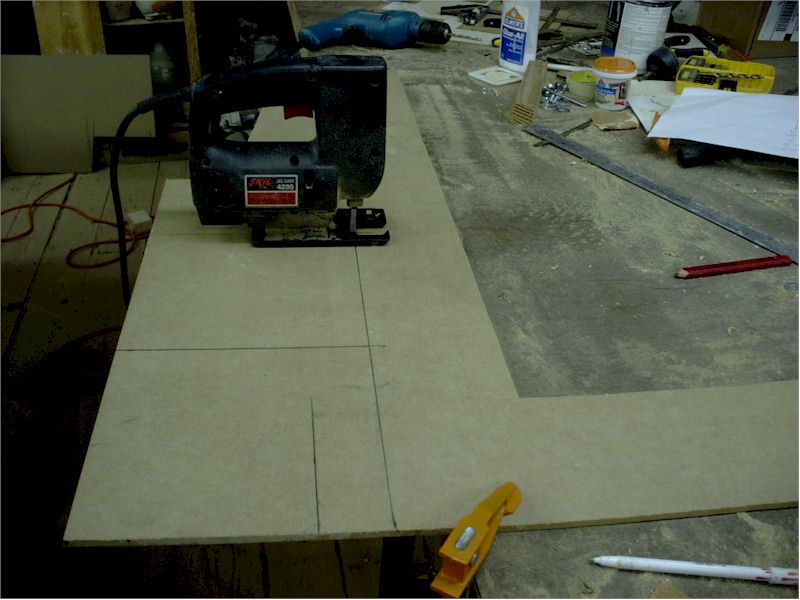
In photo #1 below you can see the facings for the main VDT type glass cockpit gauges like the PFD and the NAV displays being cut out. They are sized to match the Airbus ones....... 8 1/4" square on the exterior of the frame and 6 1/4" for that actual display itself.
They are cut out of 1/4" mdf board. These frames will be slightly thicker than the facings for the other instruments that will be cut out of 1/8" mdf.
Photo #1
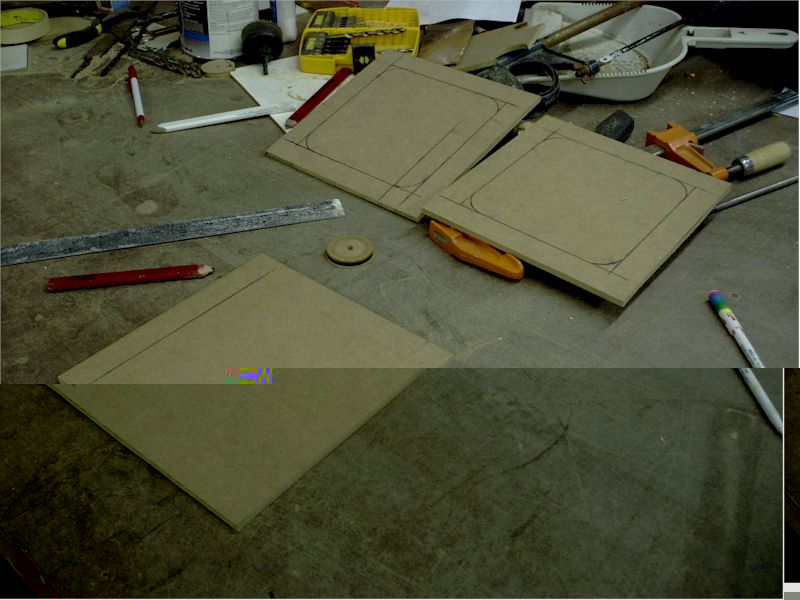
In photo #2 below you can see the markings for the hole to be cut out of each of the VDT gauge frames. The interior corners are rounded to give the displays a more realistic look. I used a hole saw cutout from another gauge as a template to draw the curve on each of the "VDT"-'s.
Photo #2
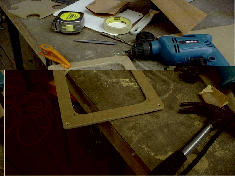
In photo #3 below, you can see small holes drilled in the mdf board to allow the jigsaw blade to be inserted so as to cut out the opening. On the corners the blade does not make the "turn" easily....so there is some "jockying" to get the cut right on the corners. A thinner "scrolling" blade would be useful here.)
Photo #3
In photo #4 below, the hole that will expose the computer monitor placed behind the main panel is cut out. The edges are rounded with sandpaper and four countersunk holes in the corners have been drilled to use for mounting screws.
Photo #4
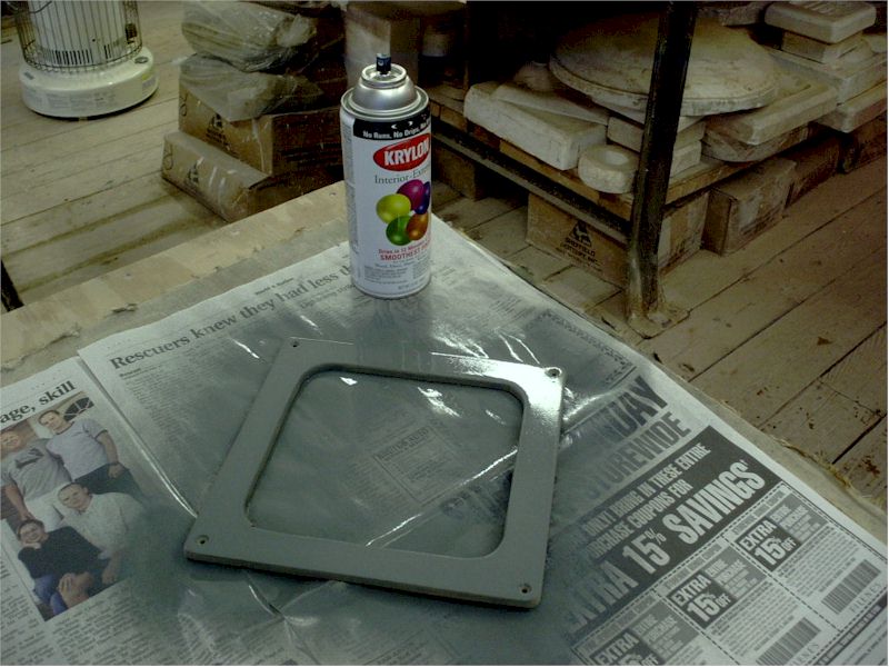
In photo #5 below you can see a coat of semi-gloss grey spray paint applied to the VDT framing. This grey is a slightly different tone that the main cockpit background grey. It makes the panels stand out a bit nicer.
Photo #5
In photo #6, I have turned my attention to the "backup gauges" that will mount next to the primary flight display and the nav display. They are cut out of 1/8" mdf "whiteboard". In this case the round hole is bored through the "gauge" with a standard hole saw.
Photo #6
In photo #7 below you can see the rectangular corners of the gauge facing cut off to more closely resemble the real gauge mountings seein in aircraft. The three countersunk holes in the corners (four on others) will be used to mount the gauge facing to the panel with flat head Phillips screws. Fake round head Philips screws will be placed into the main panel facing wood near the cut off corners to more accurately simulate the real panel mountings....although they will really hold nothing at all. All the edges have been sanded off once again.
In this photo, you can also see the altimeter adjustment switch that will function on this particular instrument.
Photo #7
In photo #8 below.... the three backup gauge facings get a coat of grey spray paint.
Photo #8
In photo #9 below you can see all the painted panel gauge and VDT facings mounted on the main instrument panel with pieces of masking tape on the rear of them holding them in place. This is simply for testing the basic locations and the "look".
The main displays have had printed paper "gauge displays" (printed from the FreeFD displays) taped onto the back to give a better feel for the eventual "look". (Continuing to look more and more realistic all the time.)
Off to the right of the #9 picture you can see the upper and lower engine instrument VDT displays too.
Photo #9
In the foreground above, you can see the start of the pilot's yoke. More on that construction later.
best,
.......................john
PS: The Goflight MFD autopilot I ordered for the simpit arrived. It works beautifully. What a pleasure it is to set what feels like a real autopilot....and watch all the stuff in the sim respond accurately and the aircraft perform the selected function accurately. It was a total "snap" to set up.
As the general layout of the glareshield portion of the simpit is becoming clearer, I have moved my attention to the main instrument panels section of the cockpit. The basic layout of the main panel will be based on the Airbus layouts with a little BAe 146-200 and Boeing 7XX thrown in.
In photo #1 below you can see the facings for the main VDT type glass cockpit gauges like the PFD and the NAV displays being cut out. They are sized to match the Airbus ones....... 8 1/4" square on the exterior of the frame and 6 1/4" for that actual display itself.
They are cut out of 1/4" mdf board. These frames will be slightly thicker than the facings for the other instruments that will be cut out of 1/8" mdf.
Photo #1
In photo #2 below you can see the markings for the hole to be cut out of each of the VDT gauge frames. The interior corners are rounded to give the displays a more realistic look. I used a hole saw cutout from another gauge as a template to draw the curve on each of the "VDT"-'s.
Photo #2
In photo #3 below, you can see small holes drilled in the mdf board to allow the jigsaw blade to be inserted so as to cut out the opening. On the corners the blade does not make the "turn" easily....so there is some "jockying" to get the cut right on the corners. A thinner "scrolling" blade would be useful here.)
Photo #3

In photo #4 below, the hole that will expose the computer monitor placed behind the main panel is cut out. The edges are rounded with sandpaper and four countersunk holes in the corners have been drilled to use for mounting screws.
Photo #4
In photo #5 below you can see a coat of semi-gloss grey spray paint applied to the VDT framing. This grey is a slightly different tone that the main cockpit background grey. It makes the panels stand out a bit nicer.
Photo #5
In photo #6, I have turned my attention to the "backup gauges" that will mount next to the primary flight display and the nav display. They are cut out of 1/8" mdf "whiteboard". In this case the round hole is bored through the "gauge" with a standard hole saw.
Photo #6
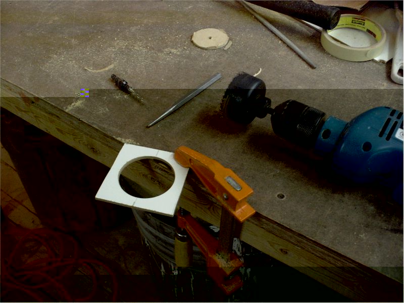
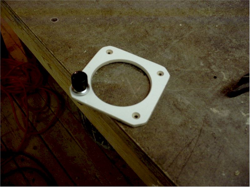
In photo #7 below you can see the rectangular corners of the gauge facing cut off to more closely resemble the real gauge mountings seein in aircraft. The three countersunk holes in the corners (four on others) will be used to mount the gauge facing to the panel with flat head Phillips screws. Fake round head Philips screws will be placed into the main panel facing wood near the cut off corners to more accurately simulate the real panel mountings....although they will really hold nothing at all. All the edges have been sanded off once again.
In this photo, you can also see the altimeter adjustment switch that will function on this particular instrument.
Photo #7
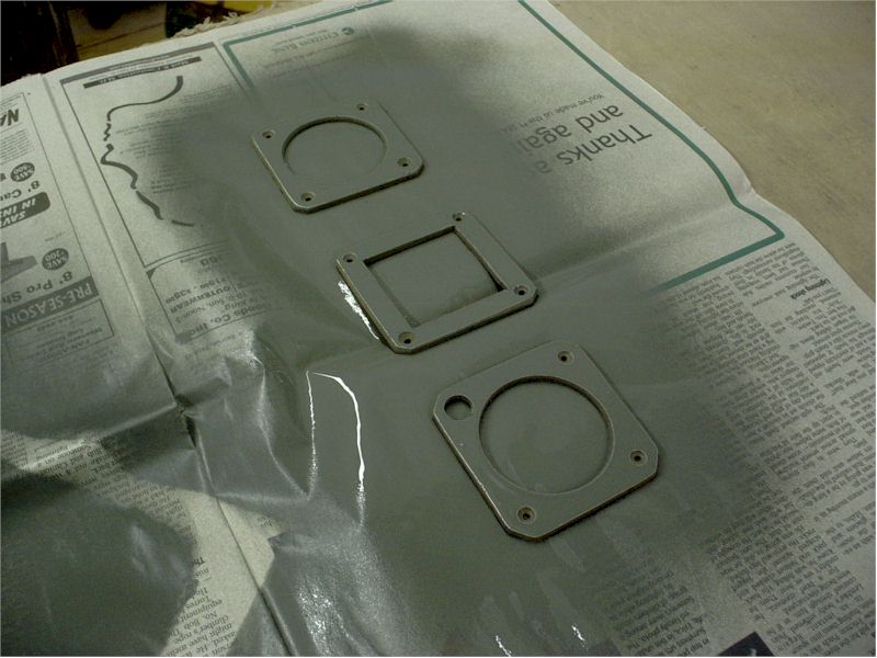
In photo #8 below.... the three backup gauge facings get a coat of grey spray paint.
Photo #8
In photo #9 below you can see all the painted panel gauge and VDT facings mounted on the main instrument panel with pieces of masking tape on the rear of them holding them in place. This is simply for testing the basic locations and the "look".
The main displays have had printed paper "gauge displays" (printed from the FreeFD displays) taped onto the back to give a better feel for the eventual "look". (Continuing to look more and more realistic all the time.)
Off to the right of the #9 picture you can see the upper and lower engine instrument VDT displays too.
Photo #9
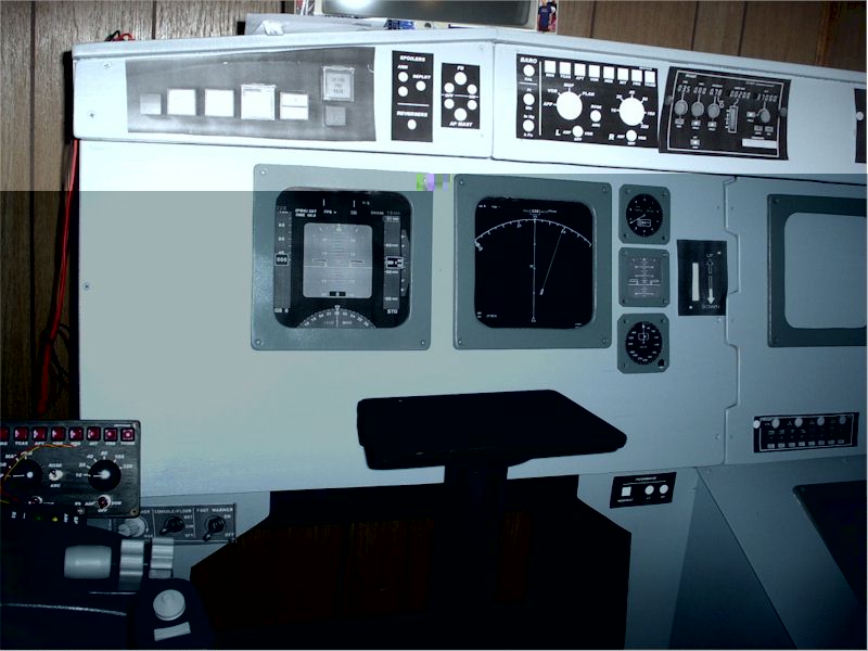
In the foreground above, you can see the start of the pilot's yoke. More on that construction later.
best,
.......................john
PS: The Goflight MFD autopilot I ordered for the simpit arrived. It works beautifully. What a pleasure it is to set what feels like a real autopilot....and watch all the stuff in the sim respond accurately and the aircraft perform the selected function accurately. It was a total "snap" to set up.